Open Hole
WSTT-I - LOGIQWaveSonic Tool
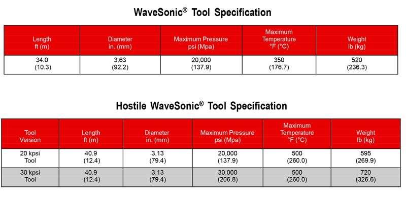
WaveSonic® Tool
The WaveSonic® crossed dipole sonic tool provides simultaneous monopole, XX dipole, and YY dipole sonic measurements. The dipole flexural wave propagation allows for the measurement of shear wave slowness in virtually all formation conditions. The compressional P-wave slowness, refracted shear wave slowness, and Stoneley wave properties are obtained from the monopole data. The shear wave slowness in two orthogonal directions can be obtained in real- time from the XX and YY dipole data. The WaveSonic tool is combinable with all standard open and cased-hole tool services. The WaveSonic tool requires a liquid filled borehole and can be used in freshwater, saltwater, or oil- based mud systems. The robust mechanical design of this tool allows for drillpipe conveyed logging, and it is not limited to the bottom of the toolstring. A hostile WaveSonic version is available for high-temperature and high-pressure applications.
The shear wave slowness in the XX and YY directions and the monopole P-wave slowness are the basic well site deliverables. The tool has 32 broadband receivers, arranged in eight rings of four receivers, to provide high-quality waveform data. The tool provides 96 waveforms (32 monopole, 32 YY dipole, and 32 XX dipole) for each firing cycle, which are recorded by the surface system. The fast and slow shear wave travel times are obtained with advanced waveform processing methods in Halliburton's reservoir evaluation services centers, strategically located throughout the world.
From the fast and slow shear wave travel times, and their orientation in the formation, the minimum and maximum principal stresses and stress field orientation can be obtained by combining oriented slowness data with overburden and analysis, wellbore stability, and production enhancement treatment design.
Sonic anisotropy analysis provides the fast and slow shear wave travel times as a simultaneous solution of 64 waveforms (32 XX and 32 YY). Anisotropy and its orientation can be used to determine the minimum horizontal stress and the orientation of natural fractures. The sonic attributes of slowness, amplitude, and frequency content can be used for identification of fractures and compressive fluids and to measure various geomechanical properties. The fast and slow shear wave travel times and their orientation, combined with P-wave slowness, allows for better 3D seismic analysis.
Applications
- Determine fast and slow wave travel times and orientation in the formation
- Calculate minimum and maximum principal stresses and stress field orientation
- Porosity estimation
- Fracture identification
- Permeability (mobility) estimation
- AVO calibration
- Synthetic seismogram
Features
- Programmable-frequency sources to minimize effects of near-wellbore alteration
- Broadband eight-level, quad receiver array for high- quality waveform data
- All 96 waveforms for each set of transmitter firings are recorded at the surface for advanced waveform processing techniques
- Combinable with all open-hole tools, including MRIL® and RDT™ tools and services
Associated Answer Products
- Shear slowness anisotropy analysis
- RockXpert2™ sand production and fracture strength analysis
- FracXpert™ fracture stimulation zoning analysis pore pressure data information is vital for geo-mechanical
- Instantaneous waveform attributes
- Stoneley derived permeability
- Stoneley reflection analysis
- Formation stress, borehole stability, and sanding potential
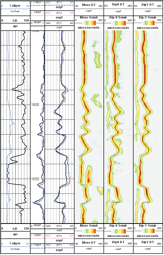
Natural gamma ray and caliper are presented in Track 1. Semblance quality data is presented in the depth track. The dipole X travel time, dipole Y travel time, and monopole P-wave travel time are presented in Track 2. Monopole semblance with the compressive wave slowness overlaid on the semblance image are presented in Track 3. The dipole X semblance with the XX shear wave slowness overlaid on the semblance image are presented in Track 4. The dipole Y semblance with the YY shear wave slowness overlaid on the semblance image are presented in Track 5.